TieQuad
This project aims to produe a low cost, lightweight quadcopter frame, accepting that parts may break in a crash, but making sure that these breakable parts are easy to manufacture and replace. It is designed to accept standard 31.5mm square electronics stacks, and 16mm motor mounting.
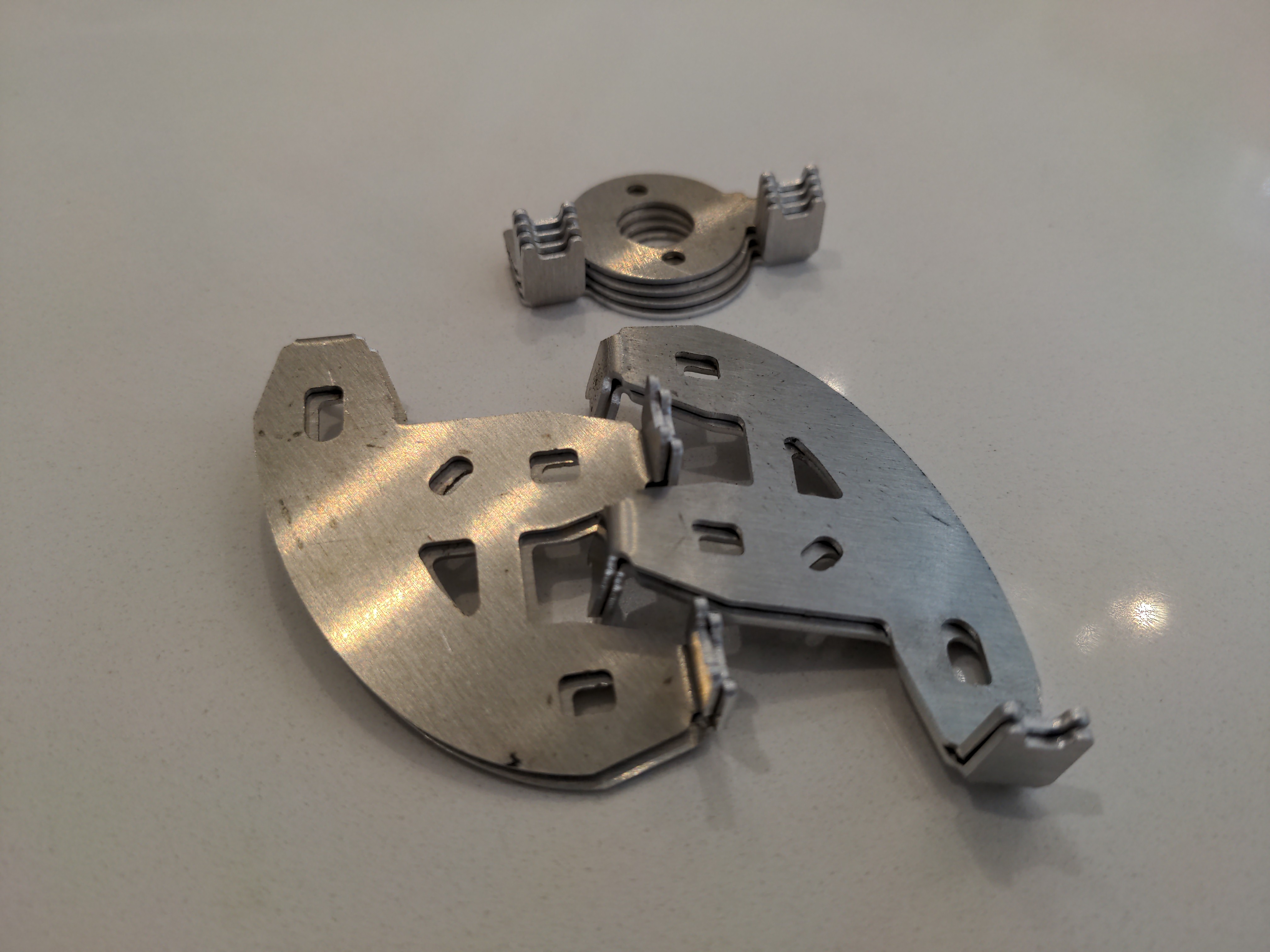
The quadcopter frame consists of four hub peices and four motor mount peices, these are intended to be CNC cut from 1mm aluminium. These peices interface with two lengths of 8-10mm box section making up the arms, crossing at the centre.
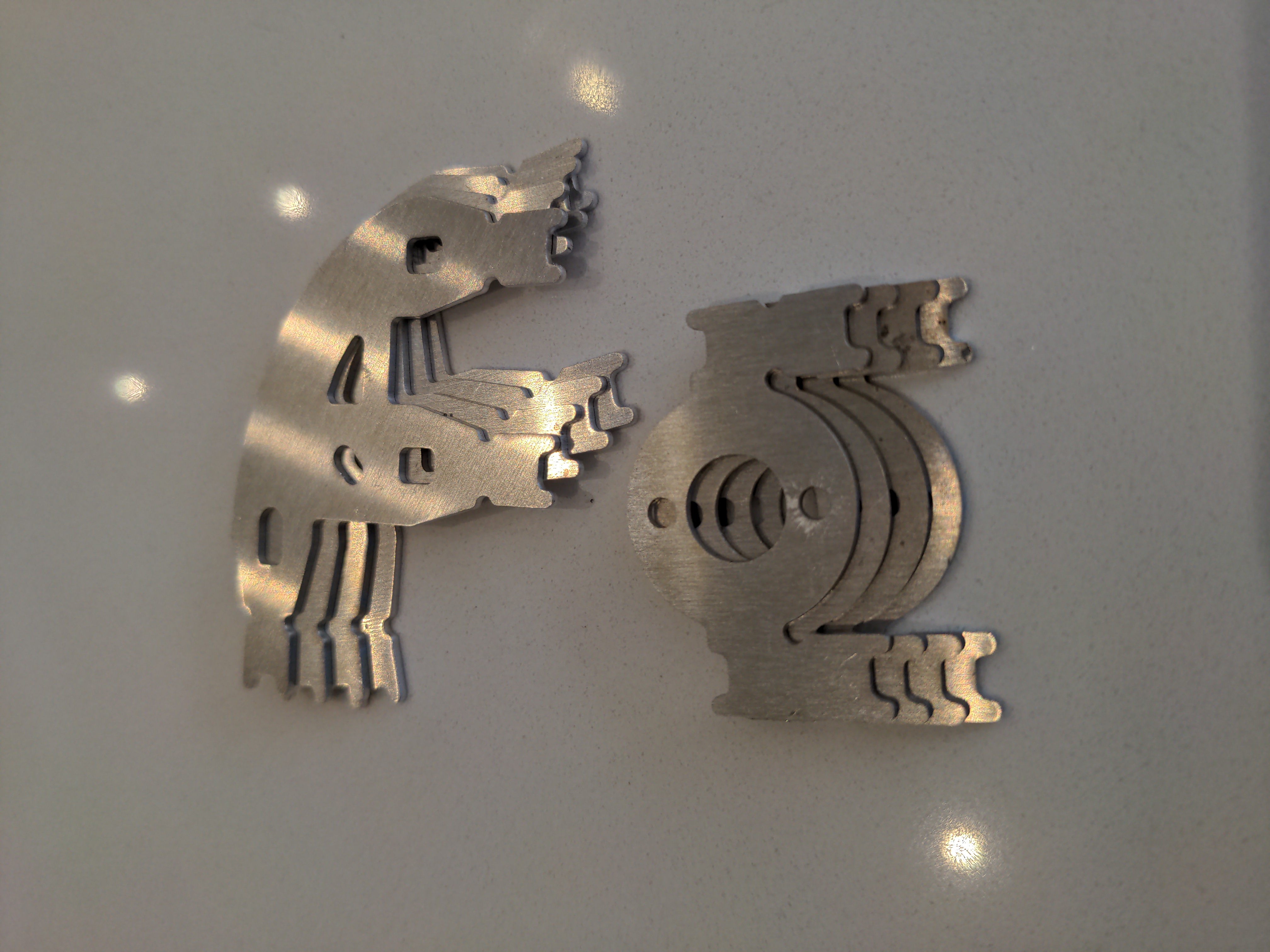
The four hub peices need to be bent in two different ways: Two of the four need to be bent with the single tab on one side up and the two tabs on the other side down, and the other two hub peices need to be bent in the opposite manner. All motor mount tabs are to be bent in the same direction. All bends are to be 90 Degrees.
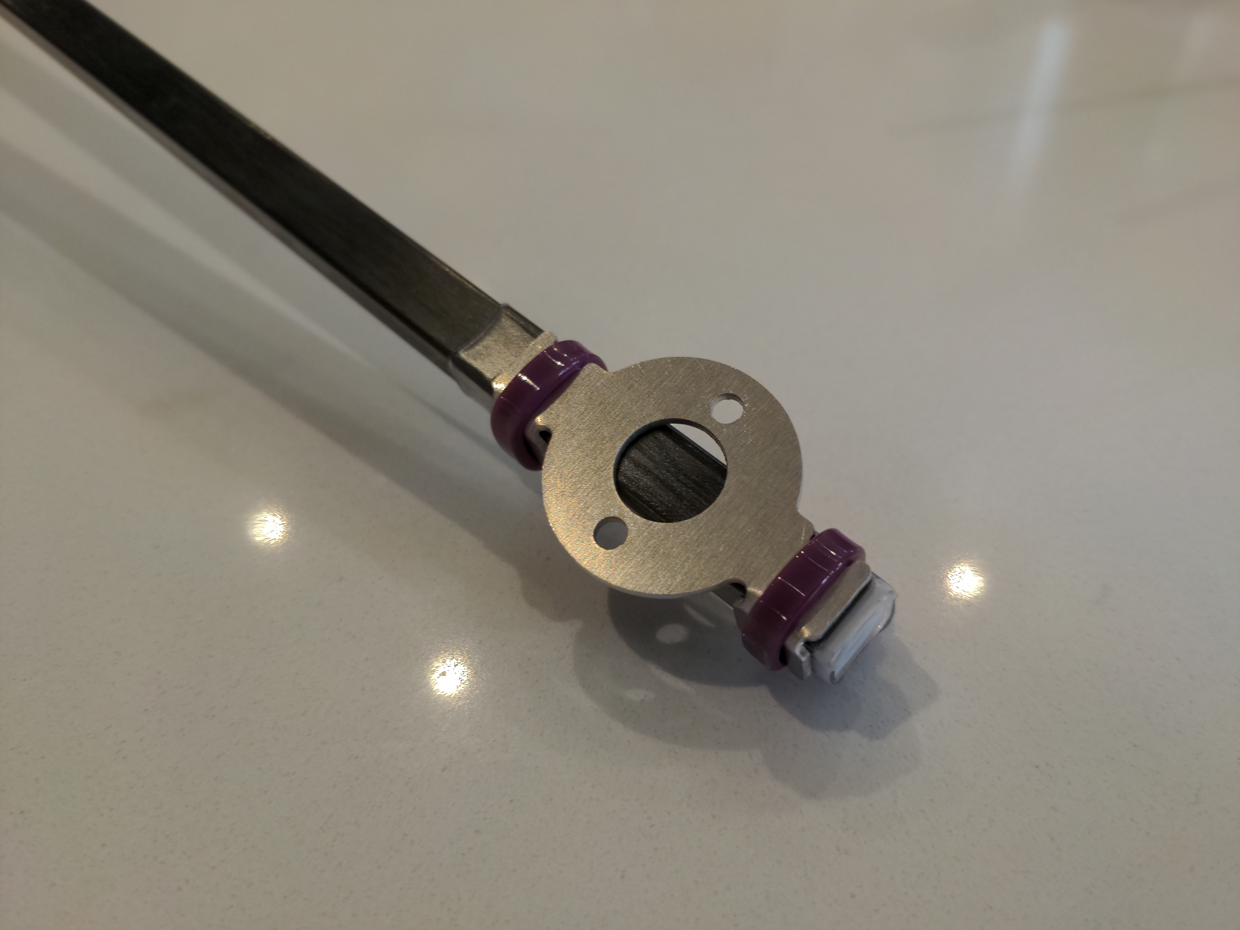
Cable ties hold the plates to the arms with friction, this means the arms require no complex manufacture at all, only cutting to length. Cable ties are to be placed over all the bent tabs, there are reliefs at the ends of the tabs to center them. The design was tested with 4mm wide cable ties.
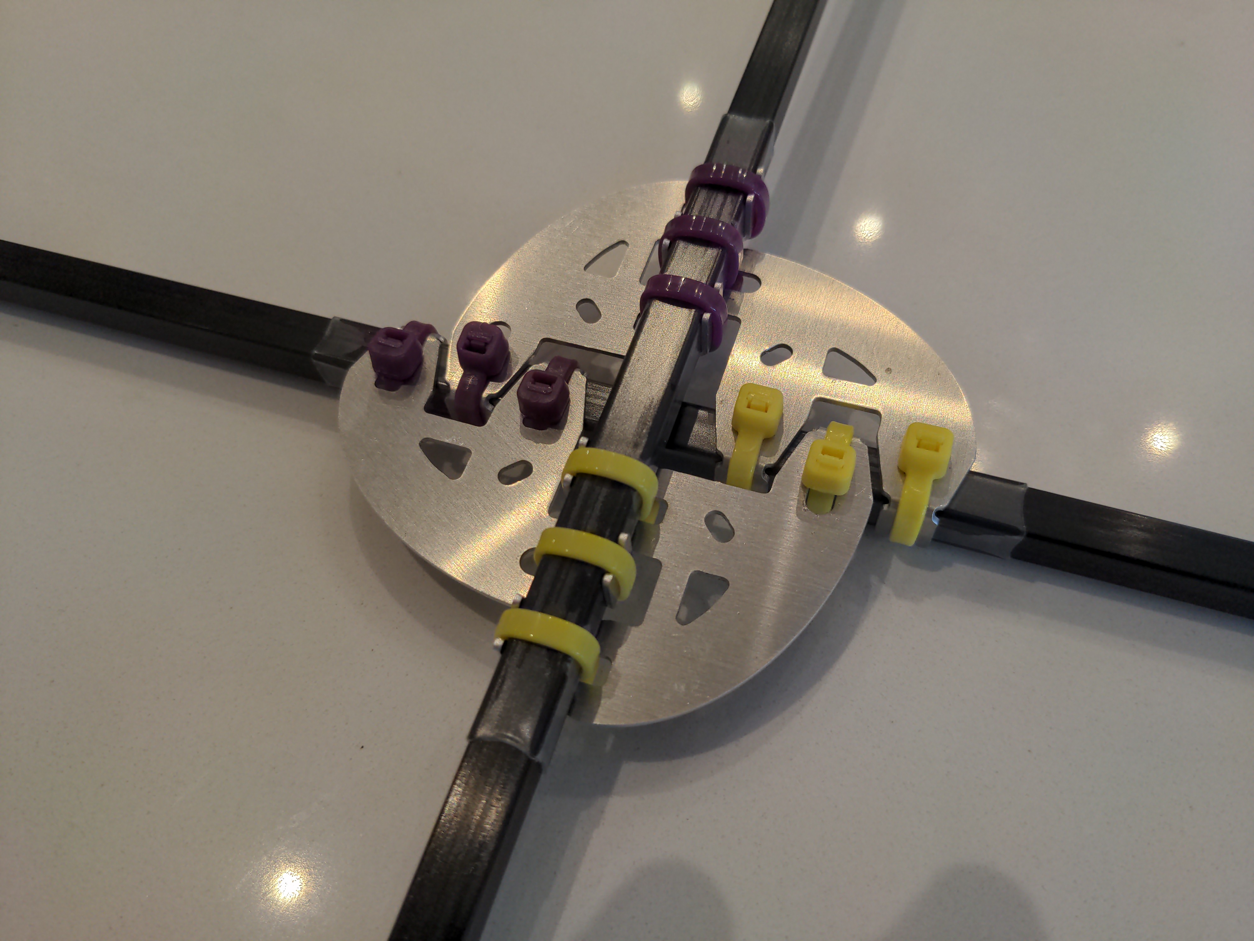
Due to the asymetric design of the motor mounts, it is recommended that the motor mounts are installed in a direction such that any stretching of the cable ties under load would cause the motor to change its thrust angle in a direction that would accentuate its gyroscopic effects on the system as a whole. i.e. for a standard quadcopter, the motor mount tabs should be on the left of the arm (when looking from the hub of the quadcopter), for clockwise spinning motors, and on the right of the arm for the anticlockwise motors.
There are extra peices available to reinforce the motor mounts and mitigate this effect for higher load applications. 8 will be required and they are to be bent and fitted under each motor mount cable tie. Half over the top of the existing mount, half contacting the bare side of the arm.
27/04/24